Alien crosstalk refers to the noise that may occur in a cable that runs alongside one or more other signal-carrying cables. It is the combination of alien near-end crosstalk (NEXT) and alien far-end crosstalk (FEXT). The alien acrosstalk between fiber jumper cables reduces the operational bandwidth of a cabling solution due to an increased level of crosstalk noise decreasing the overall signal-to-noise ratio (SNR). This additional reduction in operational bandwidth are posing threat for the performance of network infrastructure, especially for the higher-bandwidth applications. Therefore the ANSI/TIA/EIA standard committees are proposing that new NEXT and attenuation limits be considered. This pose briefly introduce some things about alien crosstalk (AXT), and the way to measure it.
Alien Crosstalk
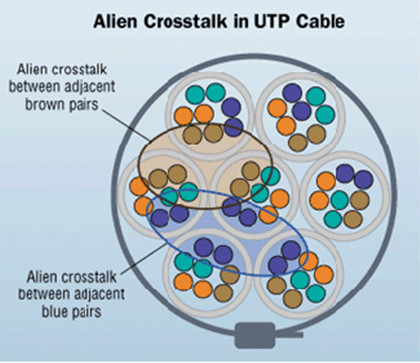
Alien crosstalk is the coupling of noise from one cable link to another. This happens if one cable is surrounded by many other cables in a bundle. Alien crosstalk can be particularly troublesome because, unlike the simple crosstalk caused by a single interfering signal, it cannot be eliminated by phase cancellation. As noted before, alien crosstalk in high-speed application is far more severer than in lower-bandwidth infrastructure. The following image shows the Alien crosstalk coupling between pairs of wires of the same color in a UTP (unshielded twisted pair) cable.

Gigabit Ethernet (GbE) technology uses an encoding method of transmitting data on all four cable pairs simultaneously and in both directions. This method is demanding on the cabling infrastructure, which might be resulted in alien crosstalk being generating within adjacent, parallel, unshielded twisted-pair (UTP) cables. People usually have the misconception that if they use shielded cables, then alien crosstalk would not be a problem. However, if the shield is not terminated correctly even a shielded system can fall foul of alien crosstalk.
How Do We Measure AXT?
Since the alien crosstalk had really bad influence in network performance, attempting to control alien crosstalk through cable design and cable installation would be a great changer to guarantee the installed network performance. In all, there are three methods that can help to control the alien crosstalk:
- Through cable design by decreasing the combined sources of noise (NEXT, FEXT, and return loss) within the system, effectively increasing the overall SNR.
- Through installation control by ensuring cables are not installed in such a way as to exacerbate the problem. This approach would preclude the use of bundled UTP cables, overfilling of conduits and trunking, or close-proximity parallel cable runs.
- Through the use of screened, balanced, twisted-pair cables.
Thanks to the above methods, we might have a chance to minimize the alien crosstalk. But we still have the need to know how to test alien crosstalk. Typically we test alien crosstalk between each pair of each disturber to each pair of the disturbed in a cable bundle. Two solutions in use today are based on test devices connecting the victim and disturber cables under test, respectively a communication channel between the devices. The following example uses the Fluke DSX-5000 testers to measure the alien crosstalk.
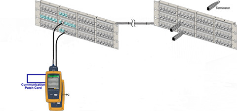
For near-end alien crosstalk testing, the main unit is connected to the victim channel, and the remote unit is connected to a disturber channel. we identify the potential Disturbed cable that is surrounded by Disturbers, not including cables’ connectors that are adjacent to gaps. For Disturbers, we pick cables in the same bundle that surround the Disturbed cable. These are the cables where the connectors are likely to cause the majority of the ANEXT. The connector shown in green identifies a potential good disturbed cable connector.

We make an ANEXT measurement with the Master unit of the DSX-5000 connected to the Disturbed (victim) at the near-end with a terminator at the far. The DSX-5000 remote unit is connected to the near-end of the Disturber with a terminator attached at the far end. The Master unit and remote are then connected together via the RJ45 communication ports to enable them to synchronise the tests being made. The measurements are then made on the Disturbed (Victim) as above for each Disturber.
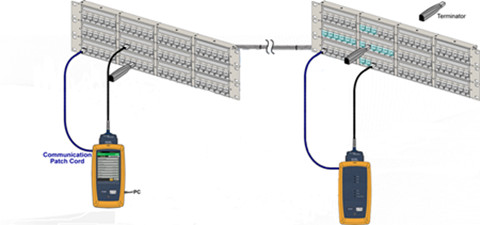
Alien Crosstalk also requires a measurement to be made from the far-end. This is the PS AACR-F (Power Sum Alien Attenuation Crosstalk Ratio Far End) measurement. This is performed in the same way as PS ANEXT but the setup is different. The Main unit is connected to the Disturbed cable connector as before. However, the remote unit is connected at the far end and the terminator at the near end as in the diagram below. In addition, the communication cable between the master and remote unit is connected through one of the horizontal RJ45 links.

During the whole testing no matter the ANEXT or the far-end AXT measurement, the Main unit of the DSX-5000 tester remains connected to the Disturbed (Victim) cable. Each time a measurement of Disturbed (Victim) is completed for one Disturber, the remote unit and the terminator are moved to the next Disturber to make the next test, this is continued until all the Disturbers in the bundle have been measured for that Disturbed cable.
Summary
Alien crosstalk measurement setup is more complex than that of general crosstalk testing. Because the alien crosstalk should be executed for a bundle of cables (at least six cables). Furthermore, more test instruments are needed for alien crosstalk, except for the Fluke DSX-5000 tester. Therefore, whether to go for a PSANEXT or ANEXT measurements, this might be a time-consuming and troublesome process. FS.COM is a professional telecom manufacturer. They not only supply plenty of optical products, such as fiber patch cables (ST-LC patch cord), transceiver modules, or DAC/AOC cables, etc, but the best services to all of customers.
评论
发表评论