With the technology evolving rapidly and new products keep coming out, optical technicians have to upgrade their knowledge accordingly. Take the UTP (unshieled twisted pair) network cabling as an example, lately telecommunication industry witnessed the evolution of copper cable from the old cat 3, cat 5 to the existing popular cat 5e and cat 6 cable (even to the cat 7 cable or cat8). Therefore, cable installers attach great importance on the TIA-568B installation. Even the experienced installer may discover the problems that they have never been aware of before. Today’s article is going to present all the detailed information necessary to complete a fully compliant TIA-568B UTP installation.
Overview of UTP Cable & TIA-568B Wiring Standard
Designed primarily for data transmission in local area networks (LANs), UTP network cable is a 4-pair, 100-ohm cable that consists of 4 unshielded twisted pairs surrounded by an outer jacket. Each pair is wound together for the purposes of canceling out noise that can interfere with the signal. So, remember to keep UTP cables as far away from potential sources of EMI (electrical cables, transformers, light fixtures, etc.) as possible. UTP cables should maintain a 12-inch separation from power cables.
In terms of the TIA-568B wiring scheme, this standard was published in 2001 to replace the 568A standard, which is now obsolete. The original purpose of the EIA/TIA 568 standard was to create a multiproduct, multivendor, standard for interoperable connectivity. The 568B standard sets minimum requirements for the various categories of cabling.
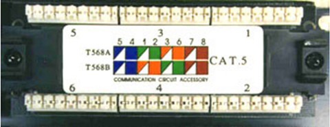
Figure 1 shows the wiring diagrams imprinted on the jacks. The upper diagram is 568A, and the lower diagram is 568B. We can clearly see the only difference between 568A and 568B is that pairs 2 and 3 (orange and green) are swapped. For detailed information about 568A and 568B, please read the previous article “How to Configure the RJ45 Pinout”.
Do's and Don'ts of UTP Installation
Before you proceed the following article, you must understand that this article is for general information only. Always check with the local store or cabling consultants when planning a network cabling installation.
Things You Should Do
For the UTP cable, or all the copper cables, you take the following instructions seriously during the installation.
- Run all cables in a Star Configuration so that all network links are distributed from, or home run to, one central hub. Visualize a wagon wheel where all of the spokes start from on central point, known as the hub of the wheel.
- The UTP cable run must be kept to a maximum of 295 feet, so that with patch cords, the entire channel is no more than 328 feet.
- Maintain the twists of the pairs as close as possible to the point of termination, or no more than 0.5"(one half inch) untwisted.
- Make only gradual bends in the cable where necessary to maintain the minimum bend radius of 4 times the cable diameter or approximately 1" radius (about the roundness of a half-dollar).
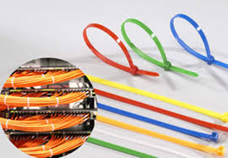
- Dress the cables neatly with Velcro cable ties (see in the below image), using low to moderate pressure.
- Use low to moderate force when pulling cable. The standard calls for a maximum of 25 lbf (pounds of force). Install proper cable supports, spaced no more than 5 feet apart.
- Use cable pulling lubricant for cable runs that may otherwise require great force to install. (You will be amazed at what a difference the cable lubricant will make)
- Always label every termination point at both ends. Use a unique number for each network link. This will make moves, adds, changes, and troubleshooting as simple as possible.
- Always test every installed segment with a cable tester to make sure the attenuation under control.
- Always install jacks in a way to prevent dust and other contaminants from settling on the contacts. The contacts (pins) of the jack should face up on flush mounted plates, or left, right, or down (never up) on surface mount boxes.
- Always leave extra slack neatly coiled up in the ceiling or nearest concealed place. It is recommended that you leave at least 5 feet of slack at the work outlet end, and 10 feet of slack at the patch panel end.
- Always use grommets to protect cable when passing through metal studs or anything that can possibly cause damage.
- Choose either 568A or 568B wiring scheme before you begin your project. Wire all jacks and patch panels for the same wiring scheme (A or B).
- Always obey all local and national fire and building codes. Be sure to firestop all cables that penetrate a firewall. Use plenum rated cable where it is mandated.
Things You Can Not Do
You should never proceed the following steps, or you will end up with permanent damage to the geometry of the cable.
- Skin off more than 1" of jacket when terminating UTP cable.
- Allow the cable to be sharply bent, twisted, or kinked at any time.
- Over tighten cable ties or use plastic ties.
- Splice or bridge UTP cable at any point. There should never be multiple appearances of cable.
- Use excessive force when pulling cable.
- Use oil or any other lubricant not specifically designed for UTP network cable pulling as they can infiltrate the cable jacket, causing damage to the insulation.
- Tie cables to electrical conduits, or lay cables on electrical fixtures.
- Install cable that is supported by the ceiling tiles. This is unsafe, and is a violation of the building codes.
- Never install cables taught. A good installation should have the cables loose, but never sagging.
- Mix 568A and 568B wiring on the same installation.
In Closing
It is rare that we can directly use the patch cables or short link copper cable to connect the devices to the switch. In most cases, we need to install cable links to remote locations from patch panels to switch ports, which is far more complex. Therefore, anyone who install UTP cabling should take the dos and don’ts seriously. Any minor mistake can easily become a nightmare in the future.
评论
发表评论