Recently Local area network (LAN) campus, enterprises backbones and data centers are upgrading to higher-density fiber counts to meet system bandwidth needs. Therefore, instead of loose tube and tight-buffered cables, network designers are turning to ribbon cables because of its ability to meet the design criteria of high connectivity density relative to cable diameter. However, ribbon cables require unique polarity designs to ensure reliable system performance as well as support ease of installation, maintenance and reconfiguration. In fact, there are three common polarity design methods, namely Method A, Method B and Method C. In today’s article, we will shed light on these three polarity standards and its impact on ribbon cable designs.
Ribbon Optical Cable Design
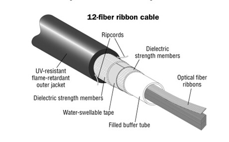
As noted before, ribbon optical cable has been regarded as the primary cable design choice for deployment in campus, building and data center backbone applications. The ribbon optical cable design offers robust performance equivalent to the stranded loose tube cable. It provides the maximum fiber density (typically consists of 12 to 216 fibers organized inside a central tube) relative to cable diameter when compared to stranded loose tube and tight-buffered cable designs. For instance, a 144-fiber unitized tight-buffered cable consumes three and a half times the effective area compared to a ribbon plenum cable of the same fiber count. Relative to copper cable, a 216-fiber ribbon plenum cable consumes the same effective area as two to three CAT 6a UTP copper cables. Figure 1 shows the inner structure of a 12-fiber ribbon cable.
TIA Ribbon Polarity Standard
The standard provides serial transmission fiber polarity guidance for systems using MTP optical connectivity. Dense wiring requirements in the LAN and data center storage area network (SAN) facilitate the use of 12-fiber array style connectors like the MTP connector. Each 12-fiber ribbon translates into six 2-fiber serial optical circuits that require polarity management that can be achieved using one of numerous methods. Fiber jumper with optical connector are usually used in different applications.
Like simplex and duplex connectors and adapters, the MTP connectors and adapters are also keyed to ensure the proper orientation is maintained when connectors are mated. With MTP connectors, this keying establishes the orientation of one fiber array in one connector relative to the array in the mating connector, but does not ensure that duplex fiber pair polarity is maintained. The standard includes guidance on three sample methods identified as Method A, Method B and Method C. Figure 2 shows a brief comparison between these three methods.
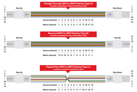
- Method A
The transmit—receive flip must happen in the patch cords, and the trunk cable is a straight through transmission, with the key up on one end, and the key down on the opposite end. Pre-assembled and field-terminated MTP-to-MTP connectorized ribbon cables called trunks are often used in these locations. No guidance is included in this standard to differentiate where the patch cord with pair-wise flips should be used and how it should be made so that it is easily recognizable from the regular duplex patch cord “straight-wired.” Because polarity is addressed in the patch cords, the end-user is ultimately responsible for managing it.
- Method B
The difference between Method A and Method B is that all components in this system are mated key-up to key-up. Method B uses a single module type wired in a straight-through configuration and standard patch cords on both ends. When the link is configured in this fashion, physical position #1 goes to physical position #12 on the other end. A module on one end is inverted so logically (label-wise) position #1 goes to position #1. This method requires advance planning for module locations in order to identify the module types and location of the inverted module in the optical link. This adds complexity to the polarity management. Using an MTP Connector key-up to key-up configuration does not allow use of an angled polished (APC) single-mode connector.
- Method C
Method C (see Figure 2) uses a pair-wise fiber flip in the trunk cable to correct for polarity. This enables the use of the same module type on both ends of the channel and standard patch cords. Because polarity is managed in the trunk, extending the links requires planning of the number of trunks in order to maintain polarity. The TIA standard does not include text regarding the ability to migrate to parallel optics for Method C, but parallel optic capability can easily be achieved with a special patch cord to reverse the pair-wise fiber flips in the trunk.
Summary
This article has listed three methods for us to consider. It is vital that end-users and system designers evaluate each method before implementing to ensure reliability, ease of installation, maintenance and reconfiguration. Only in this way can we possess the the ability to easily migrate to higher-data-rate solutions. Fiberstore offers a variety of fiber optic patch cables terminated with LC, SC, FC, and MTP/MPO connectors. Their products like ST-LC patch cord and LC-SC fiber cable are offered with the lowest price and high quality.
评论
发表评论