Subscribers are often complaint about not finding any information about fiber optics aimed specifically at them. Because most materials about fiber optics is written to train optical technicians, people who have no experience in telecommunication can not understand these industry standards. So they have to ask an optical technician for help every time they met a problem or even a tiny error. Today’s article has provided detailed information so that end users can find answers to their questions on fiber optics.
What Is Fiber Optics?
Fiber optics is the primary the medium we use to communicate today. For instance, Phones, landline or wireless, the Internet and cable TV all communicate on fiber optic cables. Fiber optics carries signals as pulses of light while copper cables carry signals as pulses of electrons. Fiber's advantages over copper result from the physics of transmitting with photons instead of electrons. In glass, optical attenuation is much less than the attenuation of electrical signals in copper and much less dependent on signal frequency.
We all know that fiber optic transmission is susceptible to interference, making it the only choice for secure communications. Unlike copper wires that radiate signals capable of interfering with other electronic equipment, fiber is totally benign. Utility companies even run power lines with fibers imbedded in the wires for both communications and network management! Although with today's applications, multimode fiber is used at 100-1000 Mb/s for datacom applications and is capable up to 10 Gb/s. Single-mode fiber offers virtually unlimited bandwidth, especially with DWDM. SC FC patch cord is one type of the fiber patch cord with SC connector on the one end and FC connector on the other end.
Understanding Fiber Optic Communications
Fiber optic links are the communications pathways between devices. A link is bidirectional, usually with signals transmitted in two directions on two different fibers. The link has a transmitter that converts electronic signals from communications equipment to optics and a receiver that converts the signal back to electronics at the other end.
Fiber optic transmitters use LEDs or semiconductor lasers to convert electronic signals to optical signals. LEDs, similar to those used everywhere for indicators, except transmitting in the infrared region beyond human perception are used for slower links, up to about 100 Mb/s. Faster links use infrared semiconductor lasers because they have more bandwidth, up to tens of billions of bits per second (Gb/s). Lasers have more power, so they can also go longer lengths, as in outside plant applications such as long distance telecommunication or CATV.
Since the light being transmitted through the optical fiber is beyond the range of human sight, you cannot look at the end of a fiber and tell if light is present. However, some links carry high power, looking at the end of the fiber, especially with a microscope which concentrates all the light into the eye, can be dangerous. Therefore, before examining a fiber visually, always check with a power meter to insure no light is present unless you know the far end of the fiber is disconnected and use a microscope equipped with a laser filter.
At the receiver end, a photodiode converts light into electrical current. Photodiodes must be matched to the transmitter type, wavelength, power level and bit rate as well as the fiber size to optimize performance. It's the receiver that ultimately determines the performance of the link, as it needs adequate power to receive data reliably. Receivers have a certain amount of internal noise which can interfere with reception if the signal is low, so the power of the optical signal at the receiver must be at a minimal level.
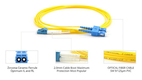
The power at the receiver is determined by the amount of light coupled into the fiber by the transmitter diminished by the loss in the fiber optic cable plant. The installer will test the cable plant for loss after construction, comparing it to a loss calculated from typical component values called the "loss budget." Transmitter power can be measured when the networking equipment is installed using a patch cord attached to the transmitter. The image above shows a SC fiber patch cord.
A Recommendation On Cabling Selection
Today, we're seeing cabling connectivity, designed to carry gigabit and 10 gigabit traffic with 850nm VCSEL transmitters, moving toward standardization on 50/125 laser-optimized fiber. If you are planning, designing, installing or using high speed premises fiber optic networks, it appears you should be recommending and using OM3 or OM4 fiber and LC connectors. One big advantage of using a full OM3 or OM4 cabling standard is that it is easily identifiable by the aqua color and cannot be interconnected with legacy cabling.
This short guide is designed to help end users pondering the choices when planning an installation and provide links to more in-depth information. If you have any other opinions about this topics, you are welcome to share with us.
评论
发表评论